8
RF Device Data
Freescale Semiconductor
MRF1535NT1 MRF1535FNT1
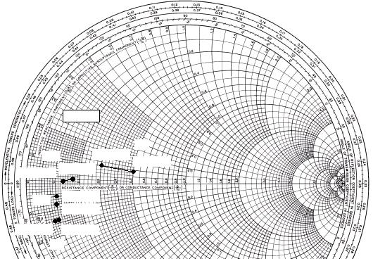
Note: ZOL* was chosen based on tradeoffs between gain, drain efficiency, and device stability.
Figure 20. Series Equivalent Input and Output Impedance
Zo
= 10
Ω
Zin
= Complex conjugate of source
impedance.
ZOL* = Complex conjugate of the load
impedance at given output power,
voltage, frequency, and ηD
> 50 %.
f
MHz
Zin
Ω
ZOL*
Ω
135 5.0 + j0.9 1.7 + j0.2
Zin
= Complex conjugate of source
impedance.
ZOL* = Complex conjugate of the load
impedance at given output power,
voltage, frequency, and ηD
> 50 %.
VDD
= 12.5 V, I
DQ
= 250 mA, P
out
= 35 W
155 5.0 + j0.9 1.7 + j0.2
175 3.0 + j1.0 1.3 + j0.1
f
MHz
Zin
Ω
ZOL*
Ω
450 0.8 - j1.4 1.0 - j0.8
VDD
= 12.5 V, I
DQ
= 500 mA, P
out
= 35 W
470 0.9 - j1.4 1.1 - j0.6
500 1.0 - j1.4 1.1 - j0.6
ZOL*
Zin
f = 175 MHz
f = 135 MHz
Zin
ZOL*
Zin
ZOL*
Input
Matching
Network
Device
Under Test
Output
Matching
Network
520 0.9 - j1.4 1.1 - j0.5
f = 450 MHz
f = 520 MHz
f = 175 MHz
f = 135 MHz
f = 450 MHz
f = 520 MHz


发布紧急采购,3分钟左右您将得到回复。
相关PDF资料
MRF1550FNT1
IC MOSFET RF N-CHAN TO272-6
MRF1570NT1
IC MOSFET RF N-CHAN TO272-8 WRAP
MRF18030ALSR3
IC MOSFET RF N-CHAN NI-400S
MRF18060ALR3
IC MOSFET RF N-CHAN NI-780
MRF18085ALSR5
IC MOSFET RF N-CHAN NI-780S
MRF18090AR3
IC MOSFET RF N-CHAN NI-880
MRF19030LSR5
IC MOSFET RF N-CHAN NI-400S
MRF19045LR3
IC MOSFET RF N-CHAN NI-400
相关代理商/技术参数
MRF1535NT1_06
制造商:FREESCALE 制造商全称:Freescale Semiconductor, Inc 功能描述:RF Power Field Effect Transistors
MRF1535NT1_08
制造商:FREESCALE 制造商全称:Freescale Semiconductor, Inc 功能描述:RF Power Field Effect Transistors N-Channel Enhancement-Mode Lateral MOSFETs
MRF1535NT1_0806
制造商:FREESCALE 制造商全称:Freescale Semiconductor, Inc 功能描述:RF Power Field Effect Transistors
MRF1535T1
制造商:FREESCALE 制造商全称:Freescale Semiconductor, Inc 功能描述:RF Power Field Effect Transistor
MRF154
功能描述:射频MOSFET电源晶体管 RF Transistor RoHS:否 制造商:Freescale Semiconductor 配置:Single 晶体管极性: 频率:1800 MHz to 2000 MHz 增益:27 dB 输出功率:100 W 汲极/源极击穿电压: 漏极连续电流: 闸/源击穿电压: 最大工作温度: 封装 / 箱体:NI-780-4 封装:Tray
MRF154MP
制造商:M/A-COM Technology Solutions 功能描述:RF POWER TRANSISTOR MOSFET
MRF1550FNT1
功能描述:射频MOSFET电源晶体管 LDMOS FET HI PWR TO272FN RoHS:否 制造商:Freescale Semiconductor 配置:Single 晶体管极性: 频率:1800 MHz to 2000 MHz 增益:27 dB 输出功率:100 W 汲极/源极击穿电压: 漏极连续电流: 闸/源击穿电压: 最大工作温度: 封装 / 箱体:NI-780-4 封装:Tray
MRF1550FT1
制造商:MOTOROLA 制造商全称:Motorola, Inc 功能描述:RF POWER FIELD EFFECT TRANSISTORS